ACTIVITIES
Activity 1.1.9 Product Design Evolution
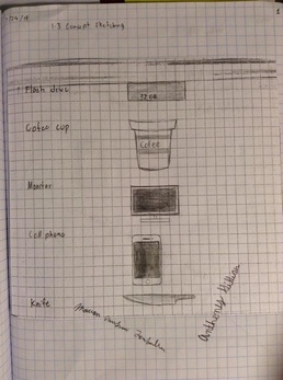
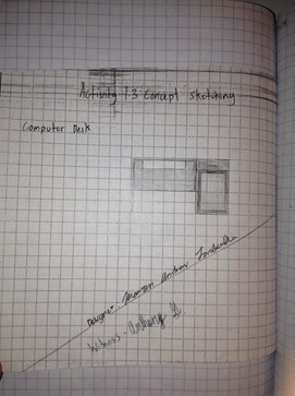
1.3 Concept Sketching
You have heard the phrase, “a picture is worth a thousand words”. Visualization through images (as opposed to words) allows people to absorb large amounts of data quickly. Sketching is an important skill for engineers and designers. Sketches provide a means through which one can quickly and clearly communicate ideas. Representing existing objects and new ideas with sketches can make the design process more effective and efficient and greatly enhance the ability of others
to understand your ideas.
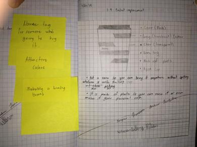
1.4 Product Improvement
1.5 The Deep Drive and Design Brief
|
Hummers®, iPods®, cell phones, clothes, and video games are just a few products that are familiar to most people. What is it about any of these products that you like? What causes you to want to buy a cell phone or an IPod? Is it the commercials or the appearance of the product? Whatever the reason, design plays a vital role in the creation and marketing of any product.
| ||
1.5 Gossamer Condor Design Brief
| 1.5_gossamer_design_brief.doc |
1.6 Discover Engineering
| 1.6_discover_engineering.odt |
| discipline_in_engineering.pptx |
1.7 what is it?
Unit 2 |
| ||
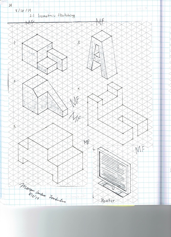
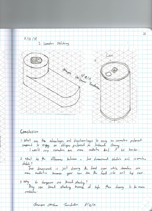
2.1a Isometric Sketching
How do reading the face of a clock and sketching isometric pictorials relate to each other? Picture a cube in your mind. All of the surfaces of the cube form right angles with their adjacent faces. If you were to draw an isometric pictorial of the cube, you would see that the edges point toward 2 and 8 o’clock, 4 and 10 o’clock, and 6 and 12 o’clock. This idea helps when sketching isometric pictorials on writing surfaces that do not have isometric grids.
Isometrics are a common pictorial used both for concept sketches and to represent designs in technical drawings.
Isometrics are a common pictorial used both for concept sketches and to represent designs in technical drawings.
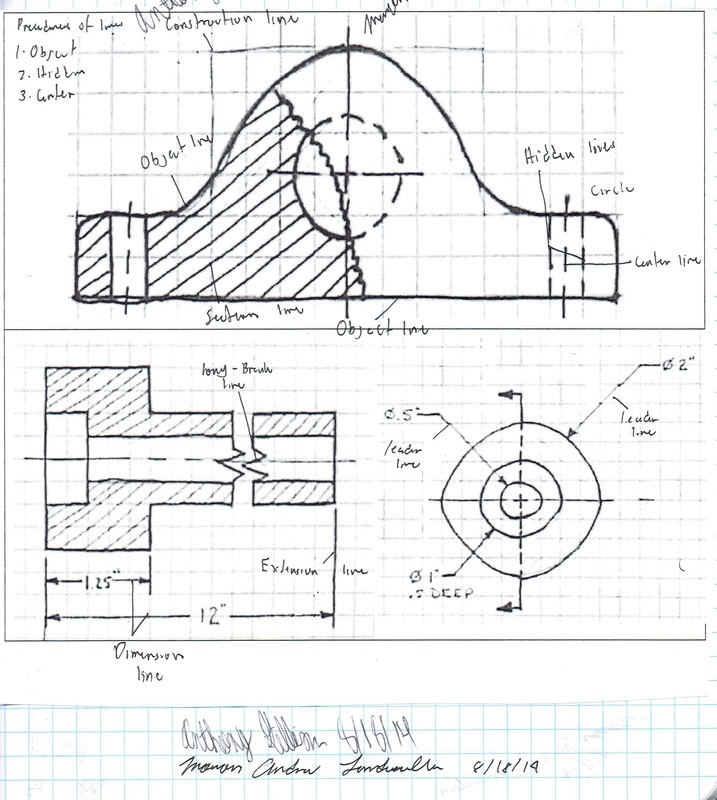
2.1b Line Conventions
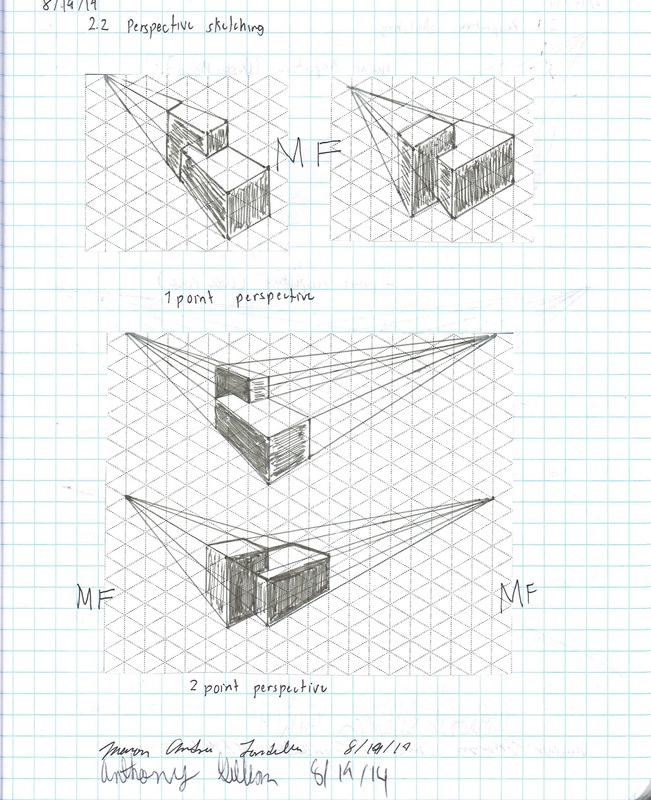
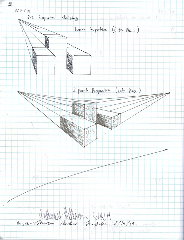
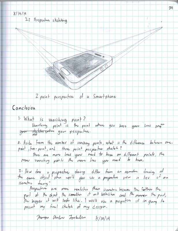
2.2 Perspective Sketching
If you can stand on a straight road and look down the road, it appears as if the sides of the road eventually narrow to one point. The center of the road vanishes when the road meets the horizon. If the road is straight enough and long enough, the sides of the road not only look like they are converging to a single point, but the road seems to appear to vanish as it meets the horizon. A similar effect occurs if you stare upward from the base of a tall building. The vertical edges of the building will appear to angle in toward each other. This effect is called perspective.
The human eye sees the world in perspective. Objects that are further away from the eye appear smaller, and edges appear to recede into the distance. Perspective sketches depict objects in much the same way that the human eye sees the world.
There are three different types of perspective drawings: one-point, two-point, and three-point perspective. The different types of sketches are frequently used by architects, industrial designers, and illustrators when representing large scale objects or environments in which the effect of distance must be taken into consideration.
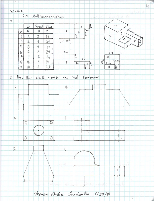
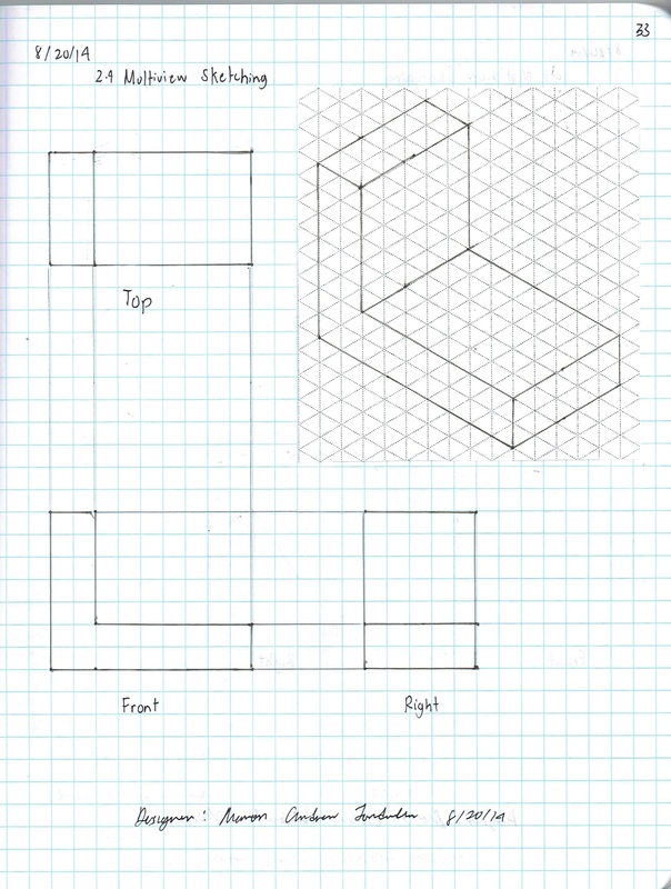
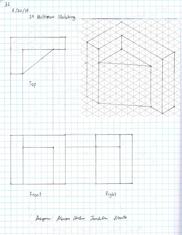
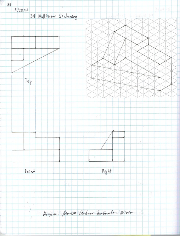
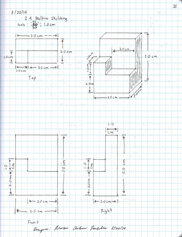
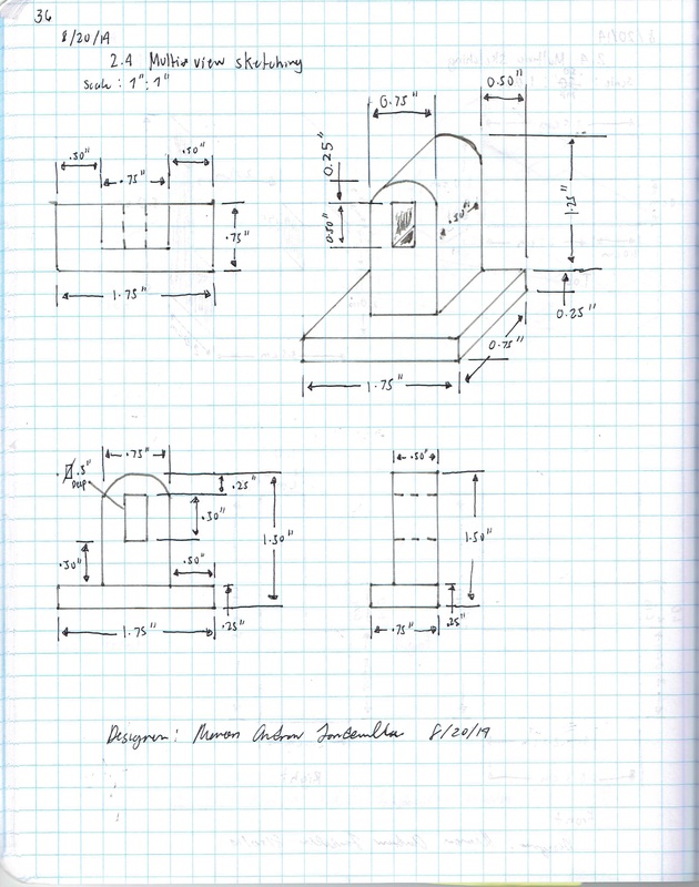
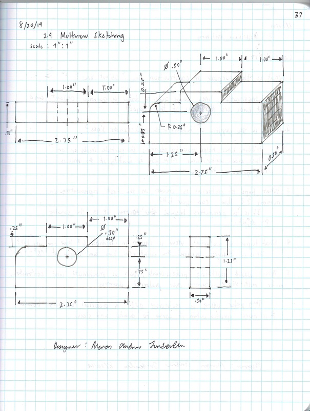
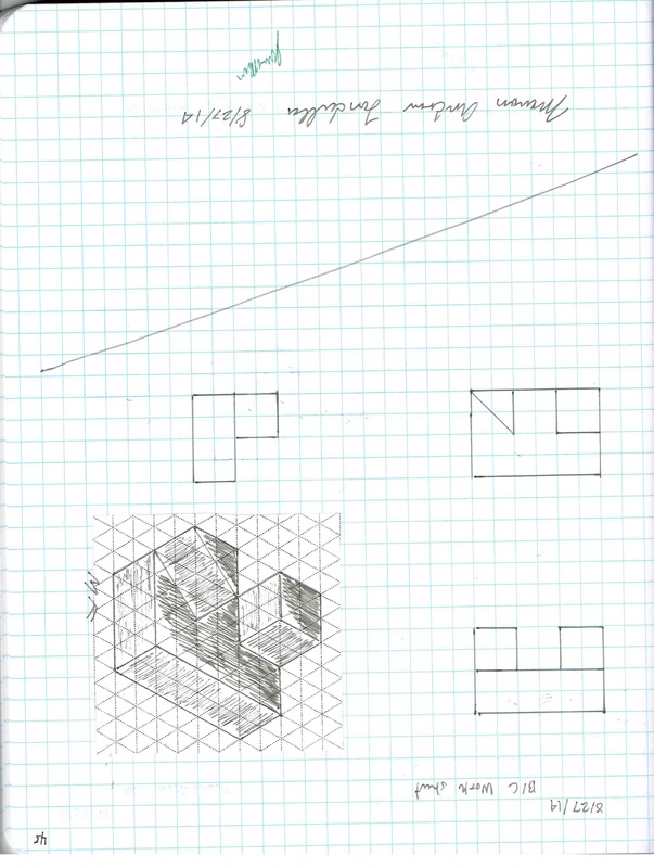
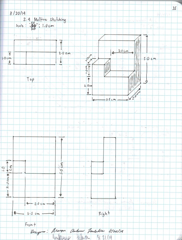
2.4 Multi-view Sketching
It’s a very common occurrence to see a product advertisement and think, “I thought of an idea for something like that just a few months ago.” People spend a lot of time in their various interest areas and envision ideas for making things work better. Spend some time with someone who has a permanent disability and see how many product ideas come to mind that would provide a degree of freedom to a person who has lost a physical capability. Coming up with wonderful ideas are only the first step in developing solutions to problems. At some point, ideas must be built.
You’ve practiced different techniques for sketching objects so that they appear to have a three-dimensional quality. These techniques are excellent for quickly communicating ideas to both technical and non-technical people. Those who make their living building ideas require a different type of drawing format. A multi-view sketch, also referred to as an orthographic projection sketch, is the standard sketch format used by engineers to communicate ideas to professionals in the building trades.
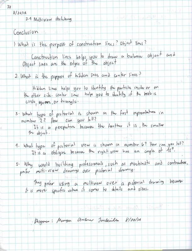
However, pictorials do not provide accurate information about the true size and shape of an object and all of its features. It is often the case that engineered objects have features and edges that are obscured by the standard surface views of a multi-view drawing. These views require hidden lines. When engineers create drawings of cylindrical objects, or objects that have holes, they must represent their axes and axes points with centerlines.
You’ve practiced different techniques for sketching objects so that they appear to have a three-dimensional quality. These techniques are excellent for quickly communicating ideas to both technical and non-technical people. Those who make their living building ideas require a different type of drawing format. A multi-view sketch, also referred to as an orthographic projection sketch, is the standard sketch format used by engineers to communicate ideas to professionals in the building trades.
However, pictorials do not provide accurate information about the true size and shape of an object and all of its features. It is often the case that engineered objects have features and edges that are obscured by the standard surface views of a multi-view drawing. These views require hidden lines. When engineers create drawings of cylindrical objects, or objects that have holes, they must represent their axes and axes points with centerlines.
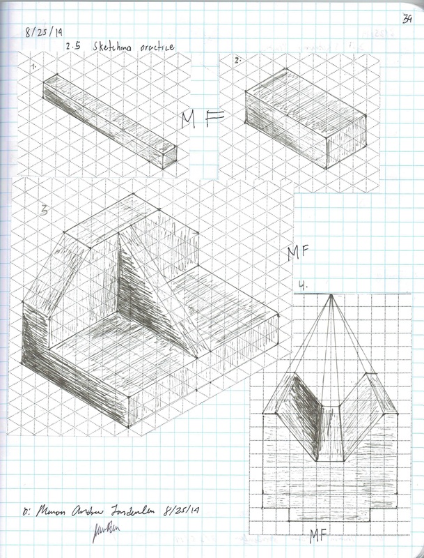
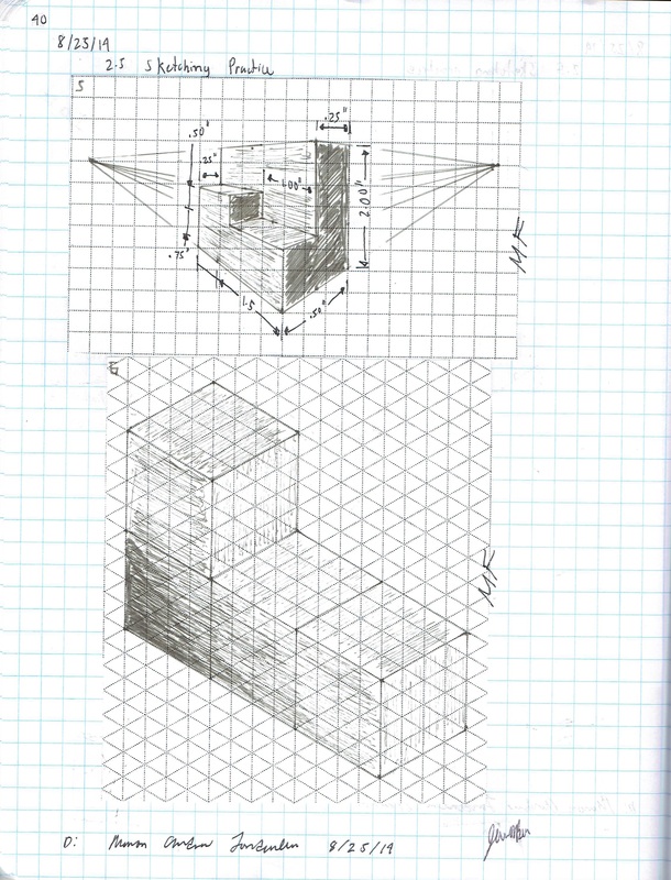
2.5 Sketching Practice
Sketching is a valuable engineering skill that needs to be developed through practice. Through practice you will be able to communicate your vision of your idea.
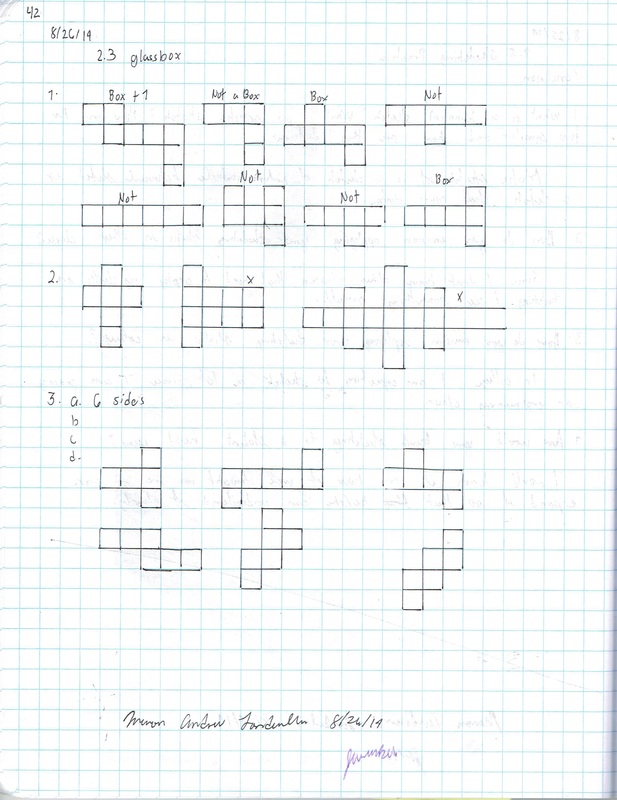
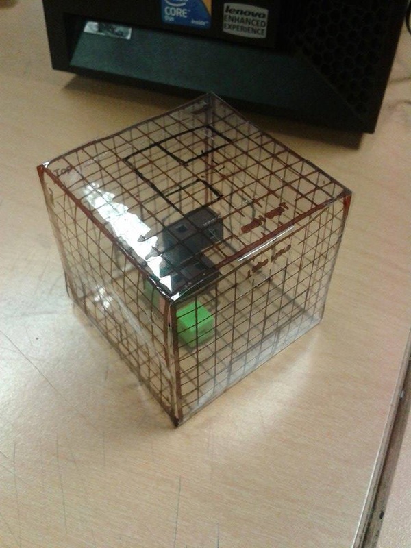
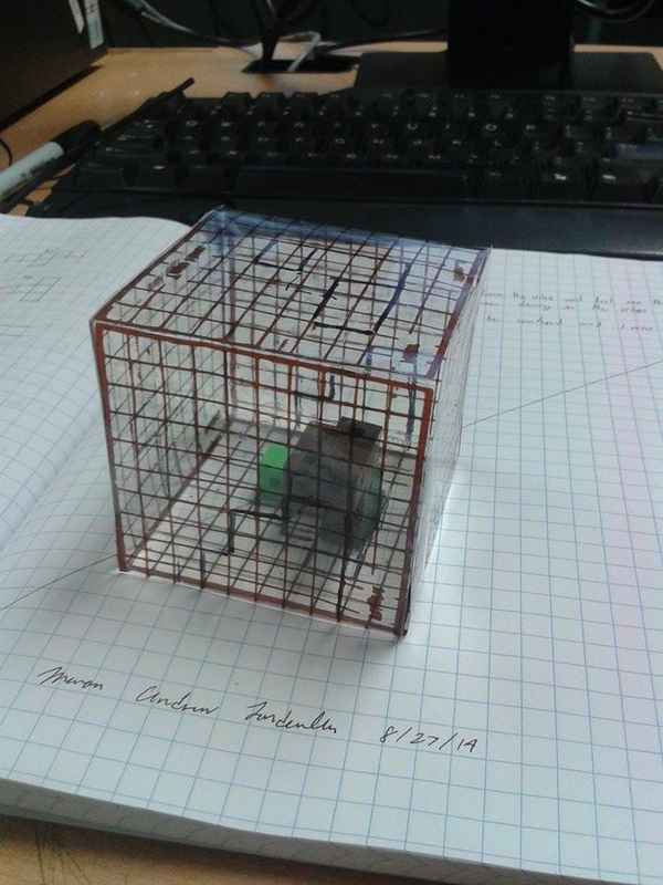
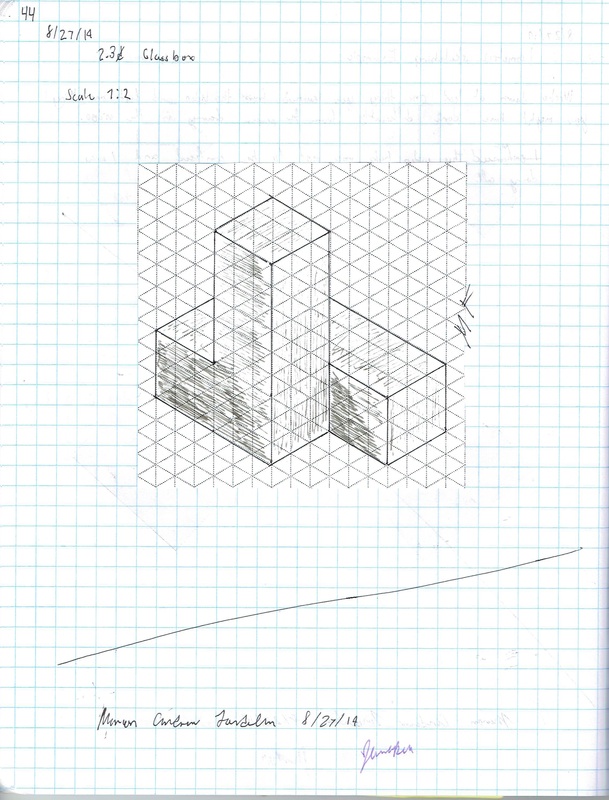
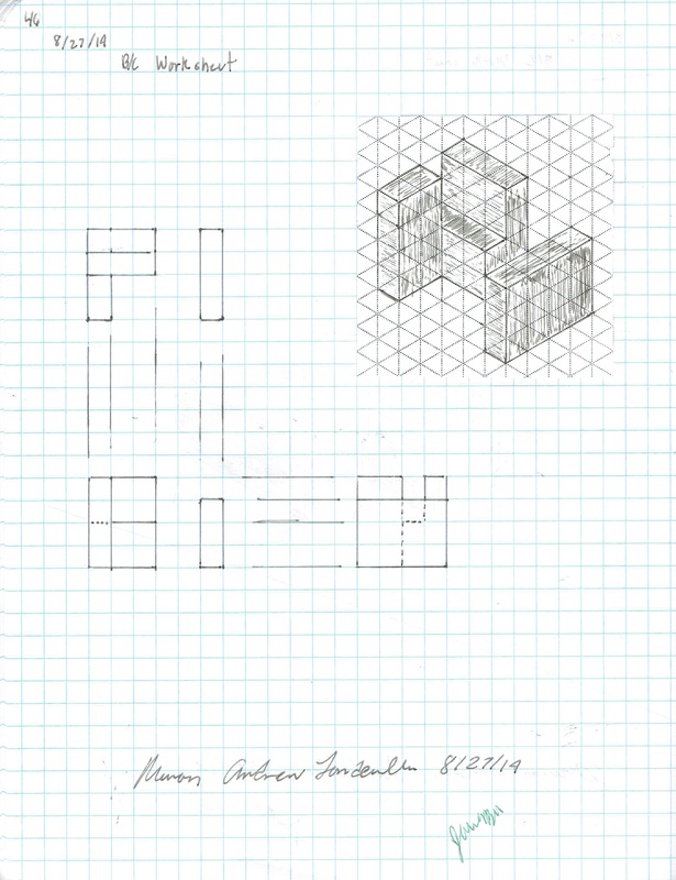
2.3 Glass Box
Objects to be produced accurately often require more than a pictorial sketch. Multi-view drawings provide an accurate representation of an object which can be used to create a physical object. Typically multi-view drawings are used to show views of the faces of the object as if the viewer is looking
directly at that face so that the line of sight is perpendicular to the face. This depicts the surface as the true size and shape.
The idea of orthogonal projections can be demonstrated using a glass box. Place an object in a glass box so that the faces of the object are parallel to the sides of the box. The features of each surface of the object can be projected onto a side of the glass box by drawing lines to indicate the object edges on the glass box surfaces.
Sketching Extension
Unit 3
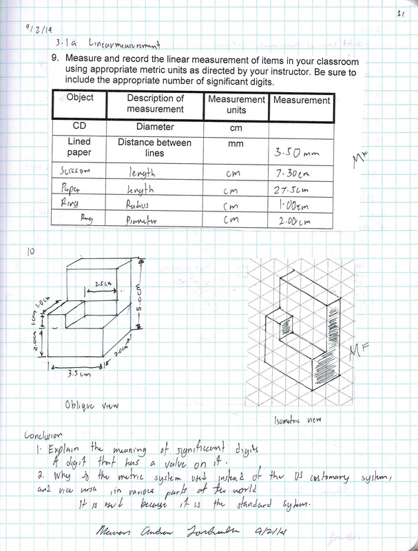
3.1a SI Measurement
Modern civilization cannot exist without measurement systems. Measurements are everywhere, and you use them every day. Every time you buy gas, check the outside temperature, or step on a weight scale, measurements are used to represent a quantity. The abilities to conduct, record, and convert measurements are necessary to understand our technological world and to carry on the business of living. The fields of science, engineering, and mathematics use measurements extensively in the processes of discovery and design.
An interesting aspect of measurement is that a single quantity can be measured in different ways. I may describe the height of a horse in hands, feet, or meters. I can give the length of a property line in chains, miles, or meters. The units commonly used to measure a quantity can change with time and across borders. In the past it was not necessary to understand the system of measurement used by people outside of your local area, but today the world is a global marketplace.
The United States is the only developed country that does not use the International System of Units. In order to participate in the global market, we must be able to understand and communicate using various measurement systems. An object that is designed in the United States may end up being manufactured in another country. Due to the global nature of technology, engineered objects must often be communicated in SI (modern metric) units.
With respect to measurements within the science, engineering, and mathematical communities, accuracy and precision of measurements is extremely important. Often the correctness of a measurement is critical to the work of scientist, engineers, and mathematicians and must be carefully considered.
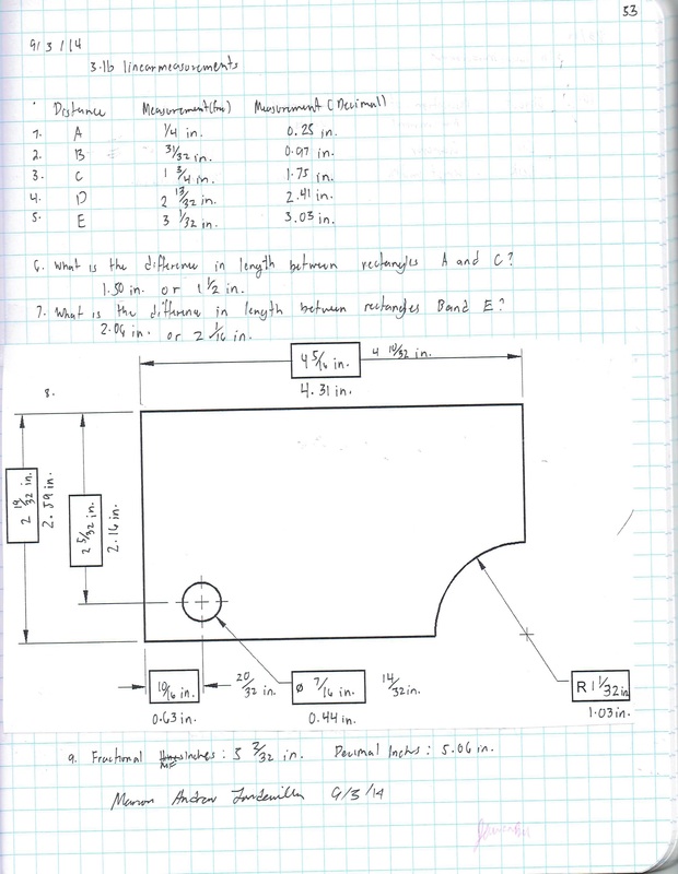
3.1b US Measurement
The United States is the only developed country that does not use the International System of Units. The U S Customary units are the accepted units of measure. However, due to the global nature of the economy, SI units are also common. In order to participate in the global market, we must be able to understand and communicate using various measurement systems.
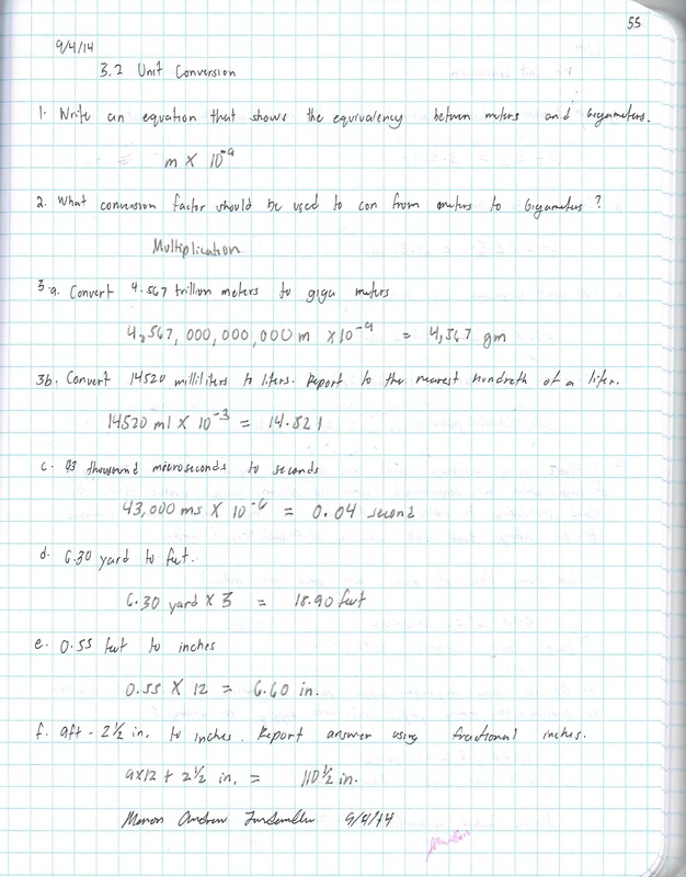
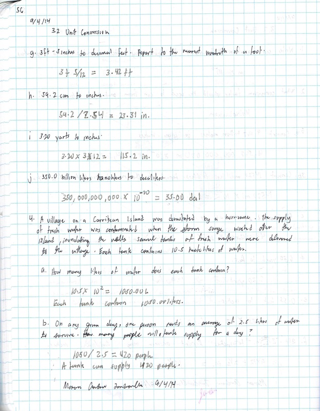
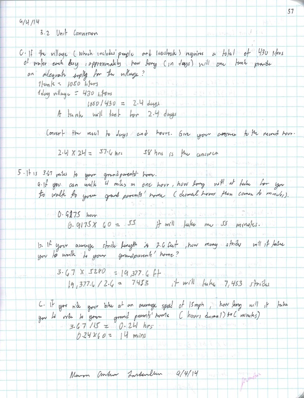
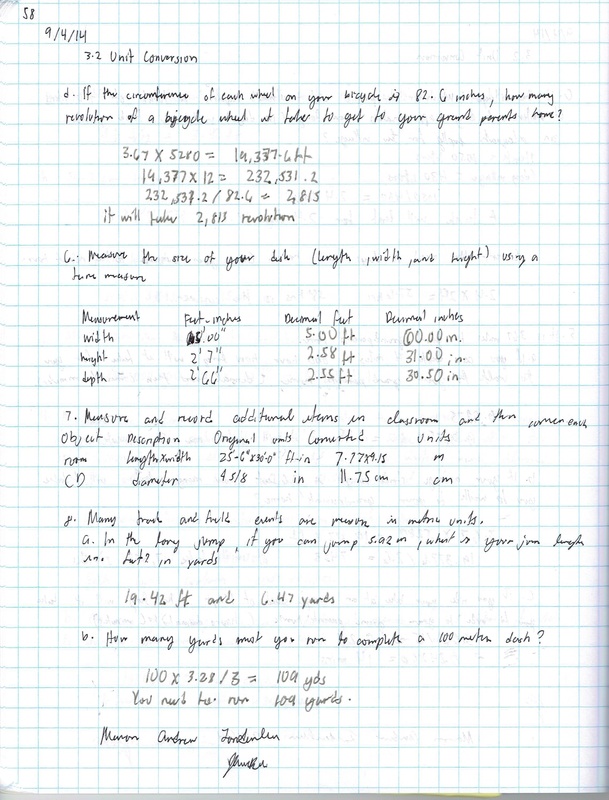
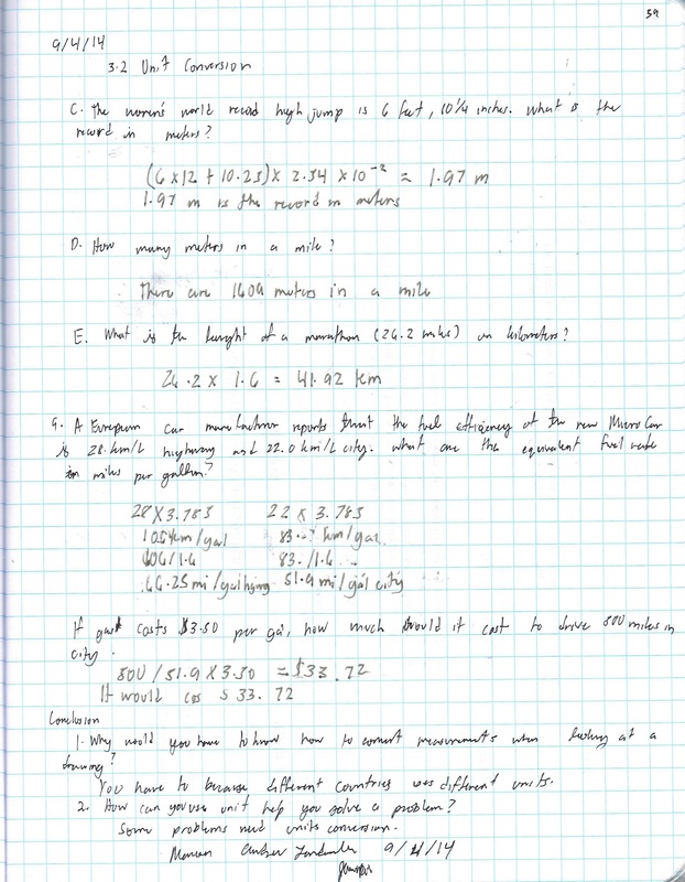
3.2 Unit Conversion
Engineers of all disciplines are constantly required to work with measurements of a variety of quantities – length, area, volume, mass, force, time, temperature, electric current, etc. It is often necessary to be able to express those measurements in different units. For example, when designing a water distribution piping system, it is important to know how much water pressure is lost as the fluid flows through the pipe. The pressure loss depends on the length of the pipe which is often measured in miles. One formula that is sometimes used to calculate pressure loss requires that the pipe length be input in feet. Therefore, it is necessary to be able to convert miles to feet.
In other situations you may be forced to work between the SI and U S Customary measurement systems. Say, for example, that as a U S company, your product is manufactured and produced based on U S Customary units. However, a European company would like a proposal to incorporate your system into their existing assembly line, the characteristics of which are based on SI units. You must be able to convert between the two systems in order to provide a proposal for a design which includes your company’s U S product.
In other situations you may be forced to work between the SI and U S Customary measurement systems. Say, for example, that as a U S company, your product is manufactured and produced based on U S Customary units. However, a European company would like a proposal to incorporate your system into their existing assembly line, the characteristics of which are based on SI units. You must be able to convert between the two systems in order to provide a proposal for a design which includes your company’s U S product.
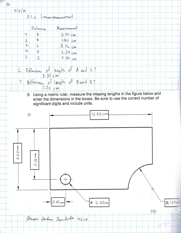
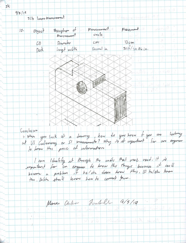
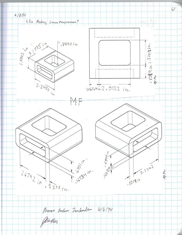
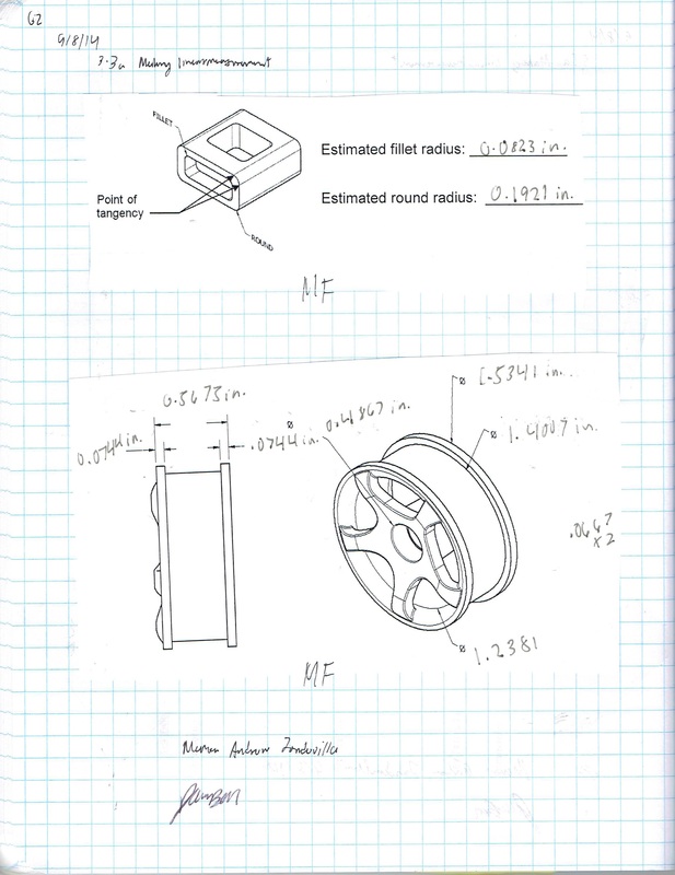
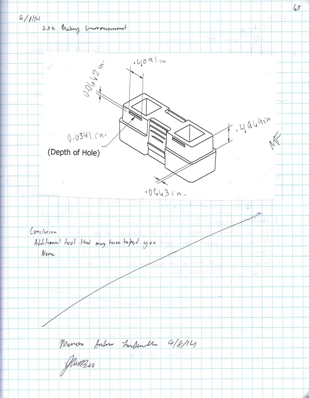
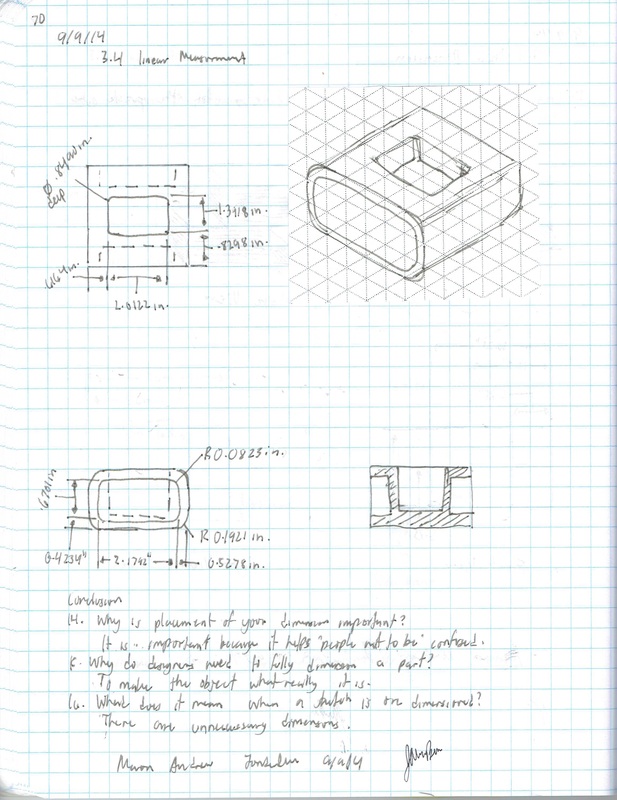
3.3 Making linearmeasurements
How thick is one of the hairs on your head? Could it be measured accurately with a standard inch scale? If the smallest increment on an inch scale is 1/16 inch, then 20 average size human hairs could fit within the space of a 1/16 inch gap. The required degree of accuracy needed is dependent on the application. If you were to build a home, a standard inch scale is perfect for laying out walls and locating window openings. A dial caliper is a precision measurement tool that is often used in the design and manufacturing of consumer products and is, perhaps, the most common of all the precision measurement tools. Engineers, technicians, scientists, and machinists all use dial calipers to assist the processes of analysis, inspection, engineering design, reverse engineering, and manufacturing.
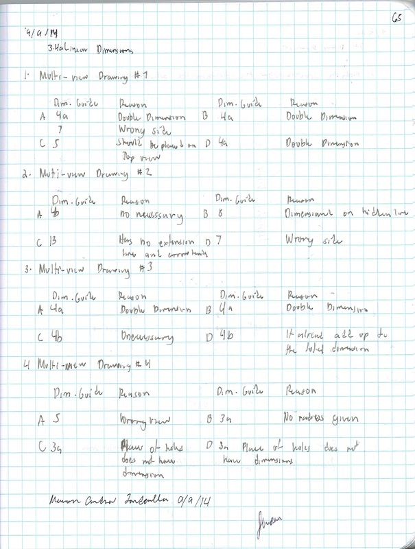
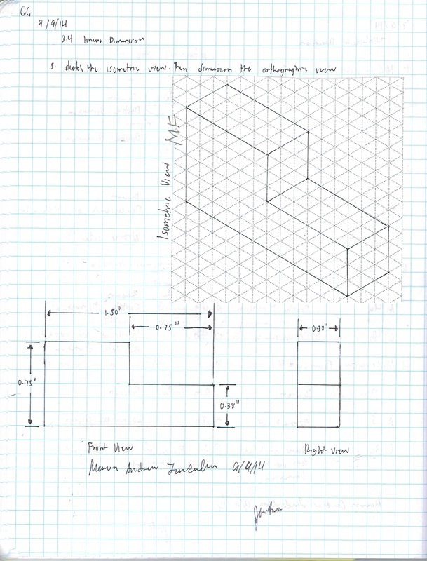
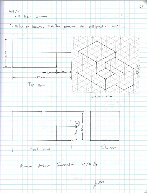
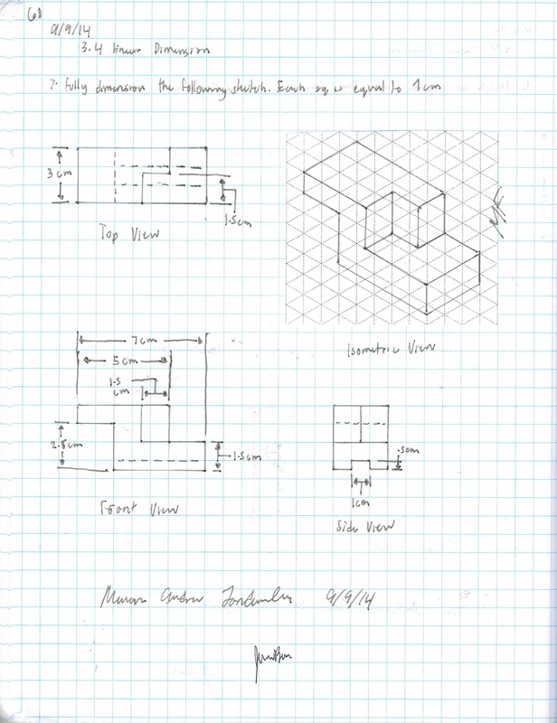
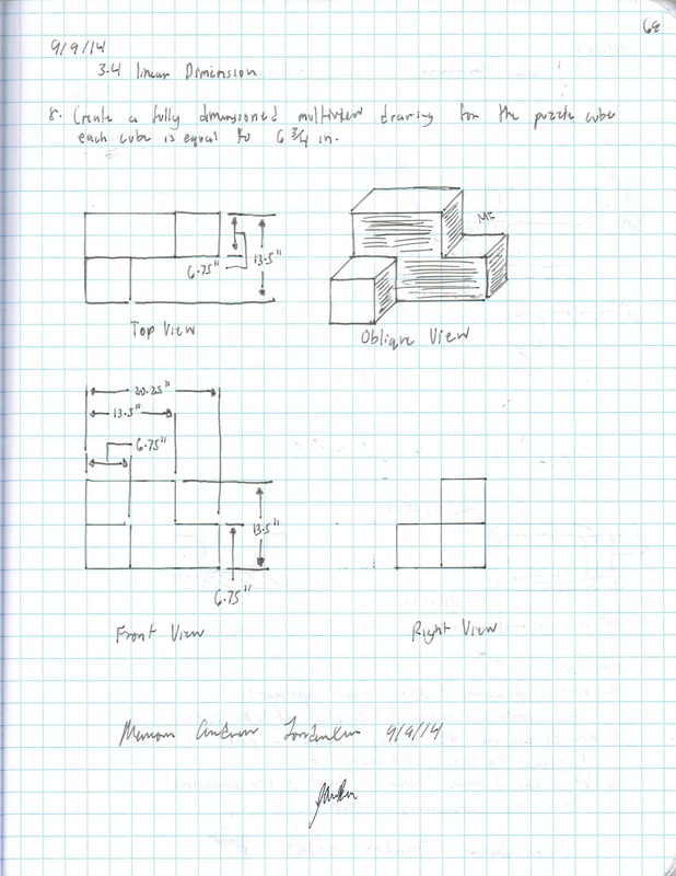
3.4 linear Dimensions
If you were given the responsibility of going to a store and purchasing a throw rug that had to fit within a room in your home, how would you communicate the shape and size of the room to the salesperson?
Given the sketching skills that you’ve developed, you would probably sketch a top view of the room on a piece of paper. This would be useful, but a sketch alone only communicates shape information.
A shape has a size that must be communicated in order to make intelligent design decisions. Information about an object’s size must be conveyed using dimensions. In manufacturing, a part must be dimensioned fully and correctly and to the proper precision. Otherwise, the part may not function properly or may not fit into an assembly as intended. Dimensioning errors can lead to a delay in production time, increased design and manufacturing costs, and a potentially unsafe product.
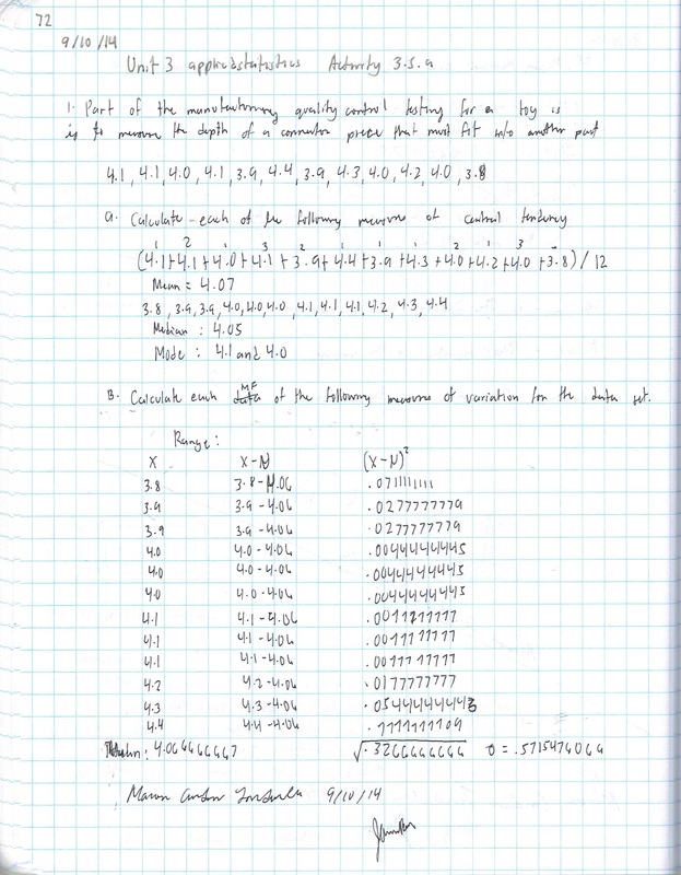
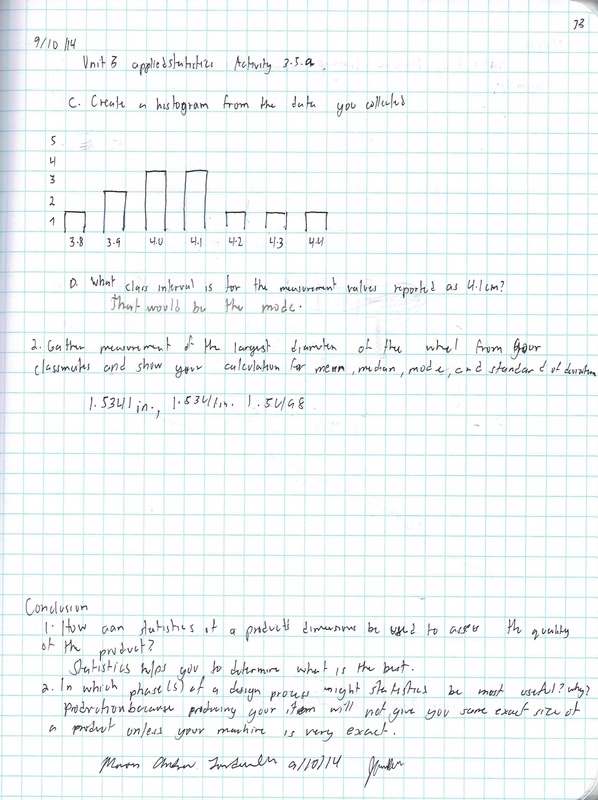
3.5 Applied Statistics
Today’s consumers are constantly trying to judge the quality of products. But what is quality? How and by whom is quality determined? Some would say the designer creates specifications, which in turn dictate the quality of a product. That quality is also based on the acceptable value of a part within a whole product. Statistics are commonly used in manufacturing processes to control and maintain quality. This activity will allow you to apply statistics in order to analyze and determine the quality of a set of wooded cubes.
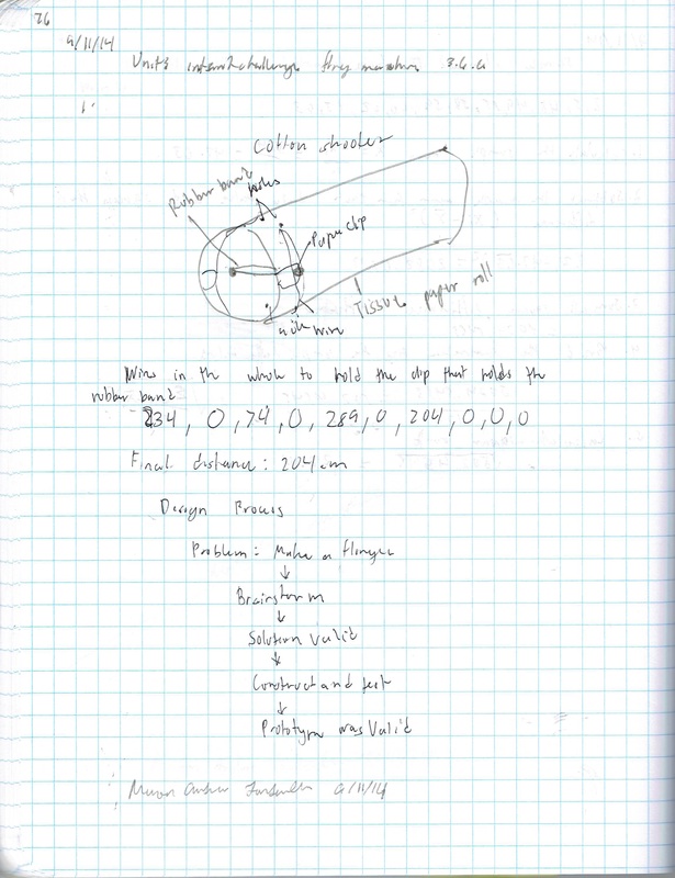
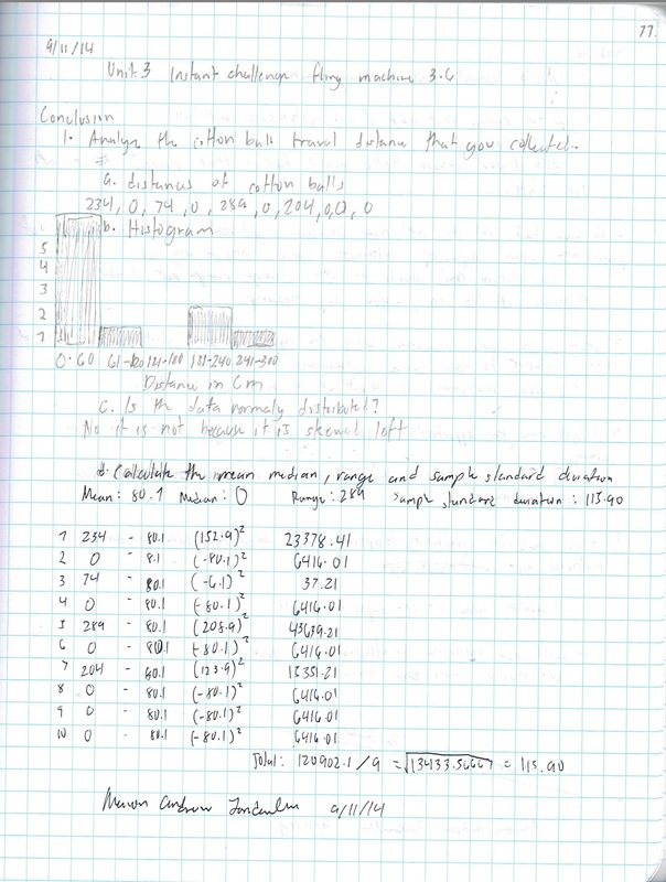
3.6 Instant Challenge Fling Machine
There are many ways to solve a problem. Sometimes it is as simple as applying a piece of duct tape. Other times it takes months or years for a product to progress from an idea into full-scale production. In this activity your team will quickly design and build a device that will send a cotton ball as far as possible through the air.
3.7 Statistical Anslysis
Engineers use various tools to make their jobs easier. Spreadsheets can greatly improve the accuracy and efficiency of repetitive and common calculations; therefore, engineers often employ spreadsheet applications in their work.
|
|
| ||

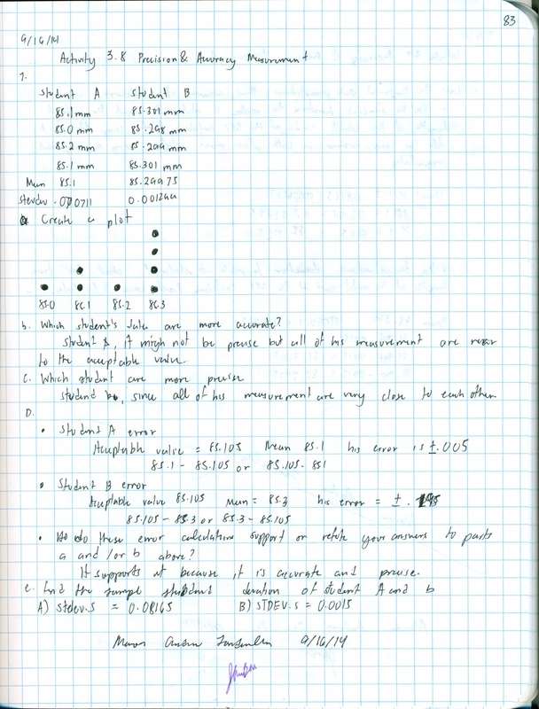
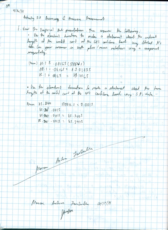
3.8 Precision and Accuracy
This concept of random and systematic errors is related to the precision and accuracy of measurements. Precision characterizes the system's probability of providing the same result every time a sample is measured (related to random error). Accuracy characterizes the system's ability to provide a mean close to the true value when a sample is measured many times (related to systematic error). We can determine the precision of a measurement instrument by making repeated measurements of the same sample and calculating the standard deviation of those measurements. However, we will not be able to correct any single measurement due to a low precision instrument. Simply stated, the effects of random uncertainties can be reduced by repeated measurement, but it is not possible to correct for random errors.
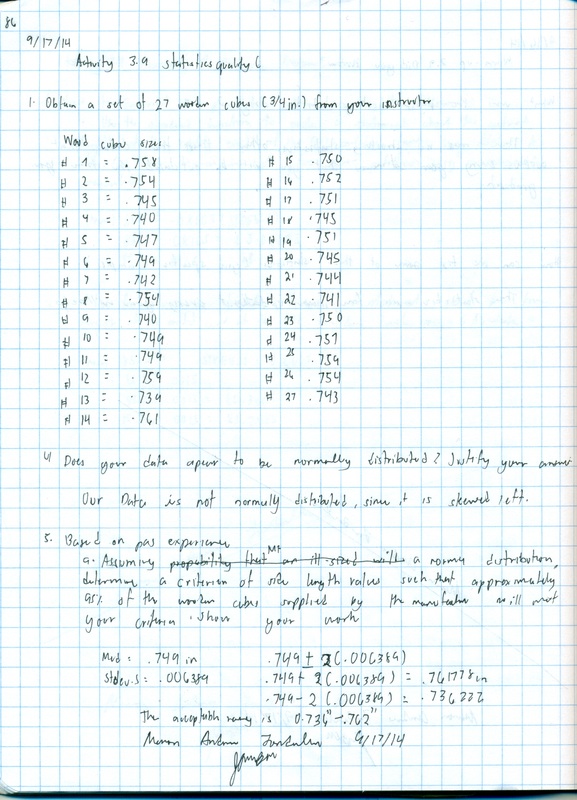
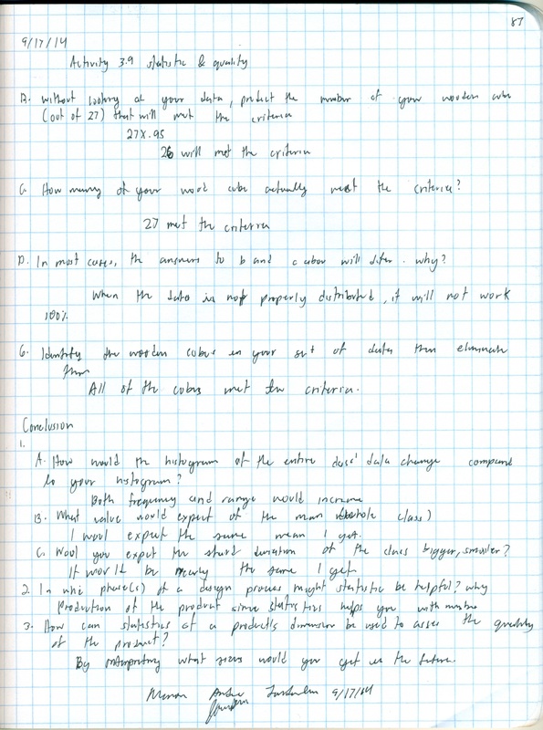
3.9 Statistic and Quality
Today’s consumers are constantly trying to judge the quality of products. But what is quality? How and by whom is quality determined? Some would say the designer creates specifications, which in turn dictate the quality of a product. That quality is also based on the acceptable value of a part within a whole product. Statistics are commonly used in manufacturing processes to control and maintain quality. This activity will allow you to apply statistics in order to analyze and determine the quality (as measured by the consistency of the size) of wooden cubes. The wooden cubes will be used in the Puzzle Cube Challenge in the next Unit. You will design and construct a puzzle cube as part of the challenge. The consistency in size of the wooden cubes will affect the quality of your final product.
| 3.9.xlsx |
Unit 4
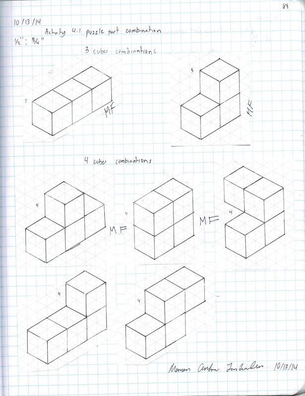
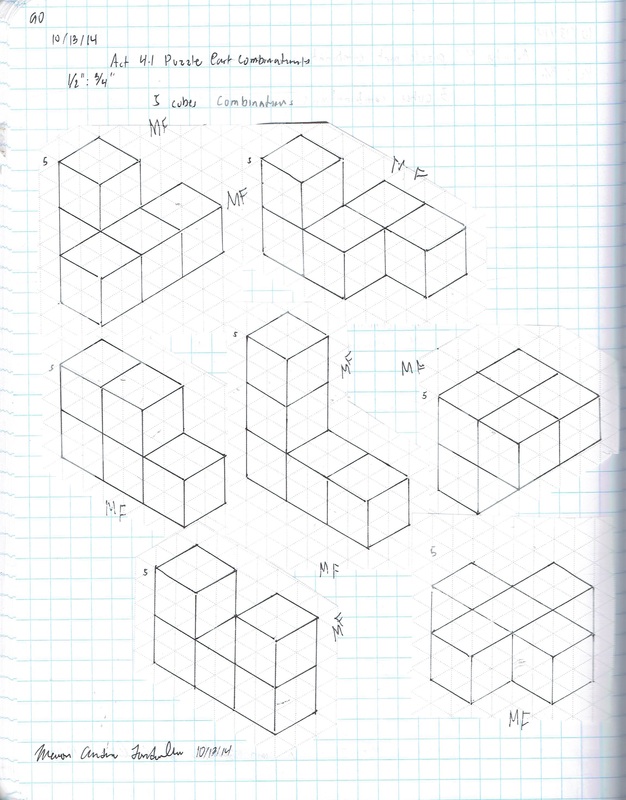
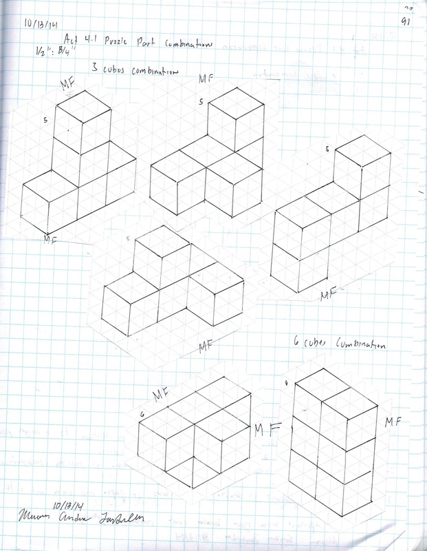
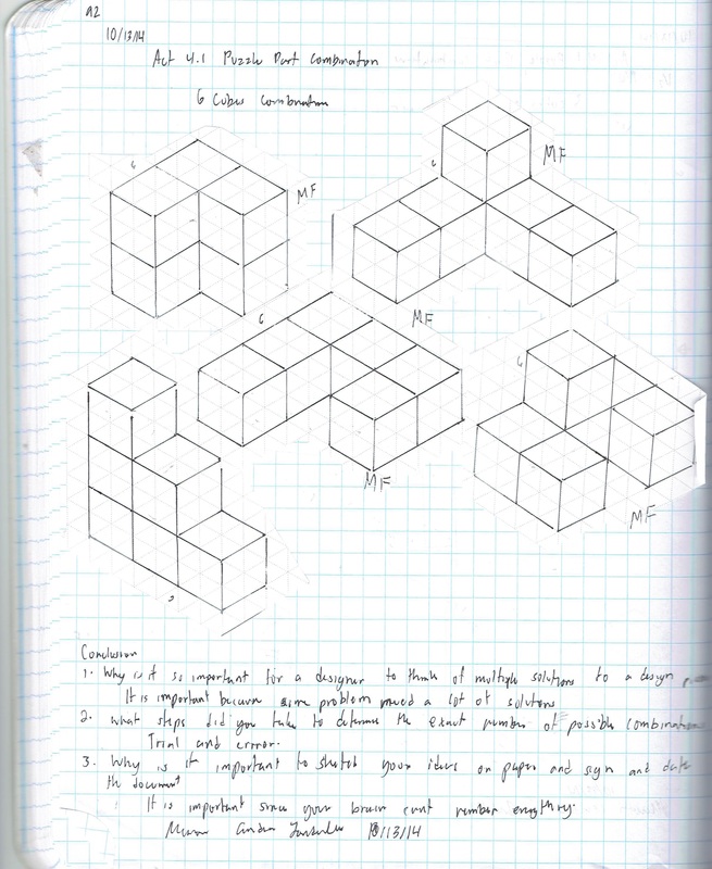
4.1.a Puzzle Part Combinations
Have you ever looked at a series of letters and been asked to come up with as many words as possible out of the list of letters? Have you ever looked at a series of numbers and been asked to figure out what code, sequence, or combination would result from the number series? Designers try to exhaust all possible combinations or solutions to an existing problem until the most intuitive solution comes along. Brainstorming several times throughout a project is very common when designing new products.
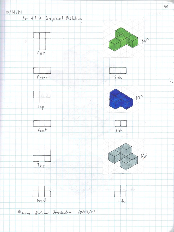
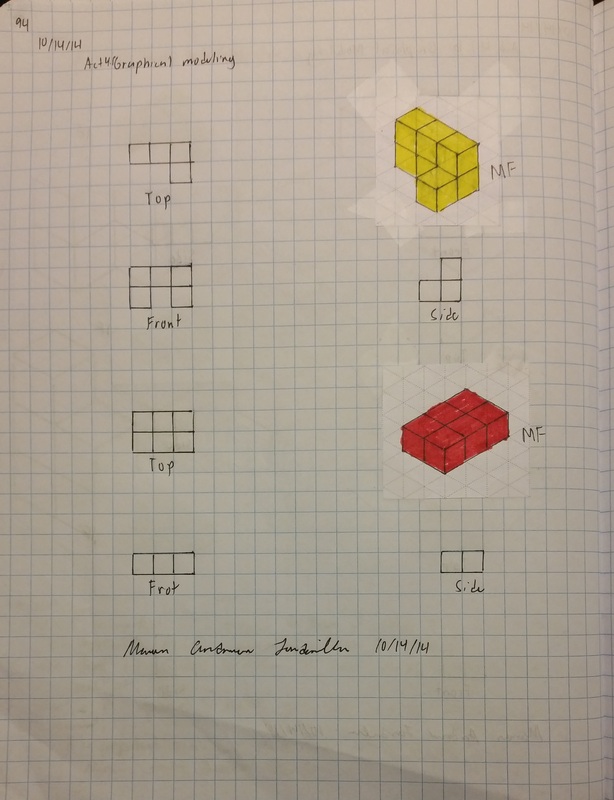
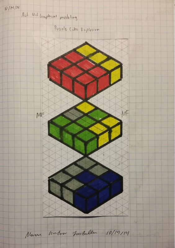
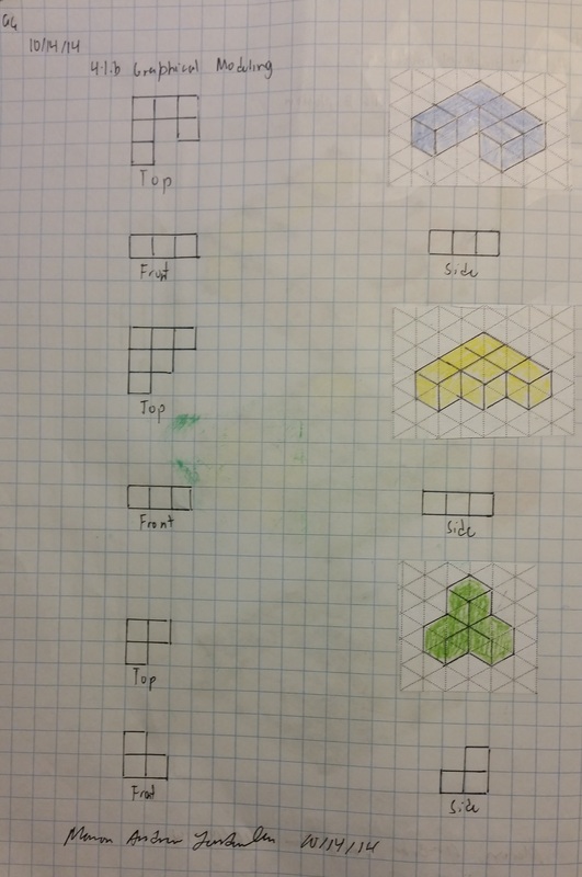
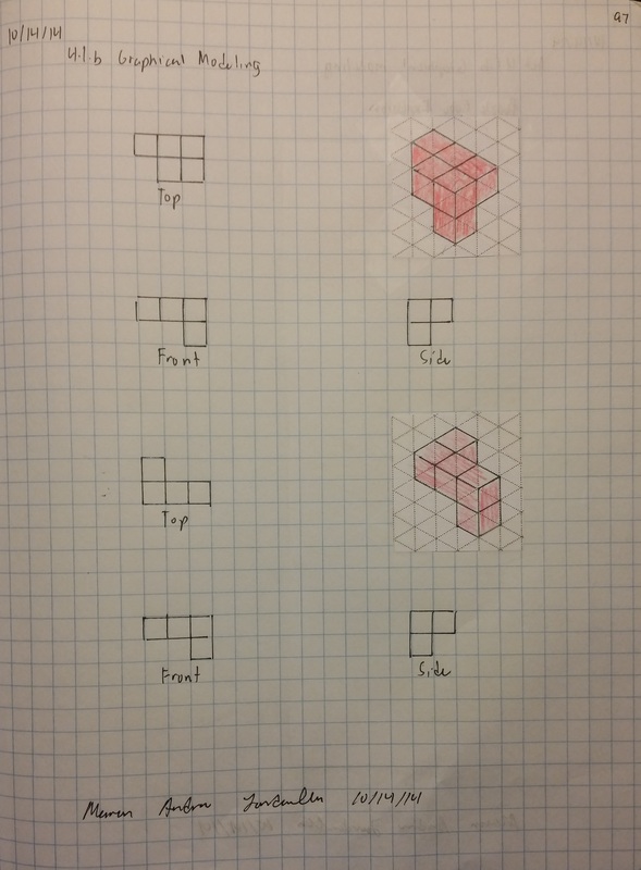
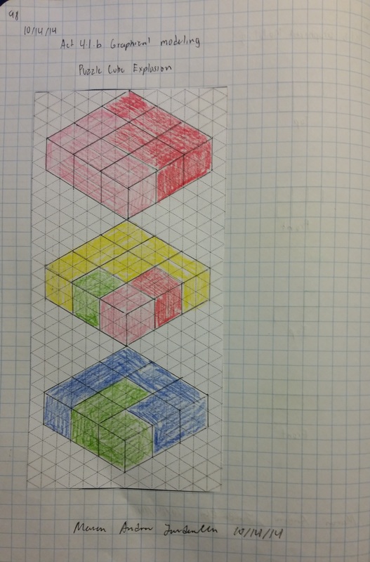
4.1.b Graphical Modeling
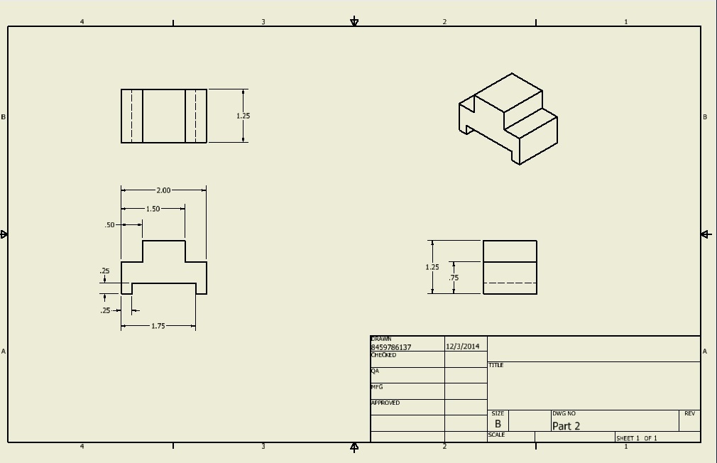
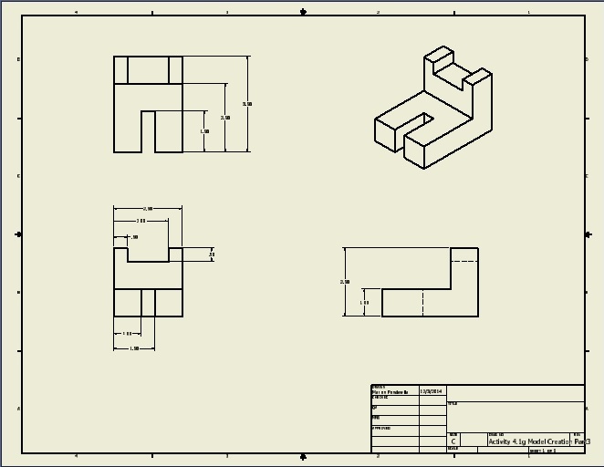
Technical drawings are used to communicate engineering designs to those who will build the product. In order that the drawings are interpreted correctly by all stake holders, the drawings should be created using accepted standard practice and should include all information necessary to correctly manufacture and/or assemble the product.
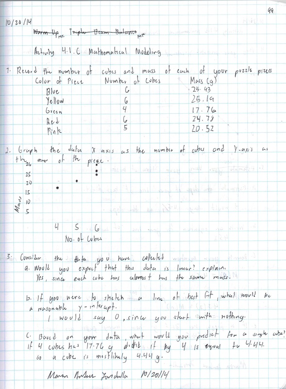
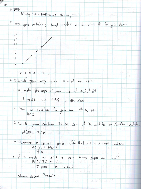
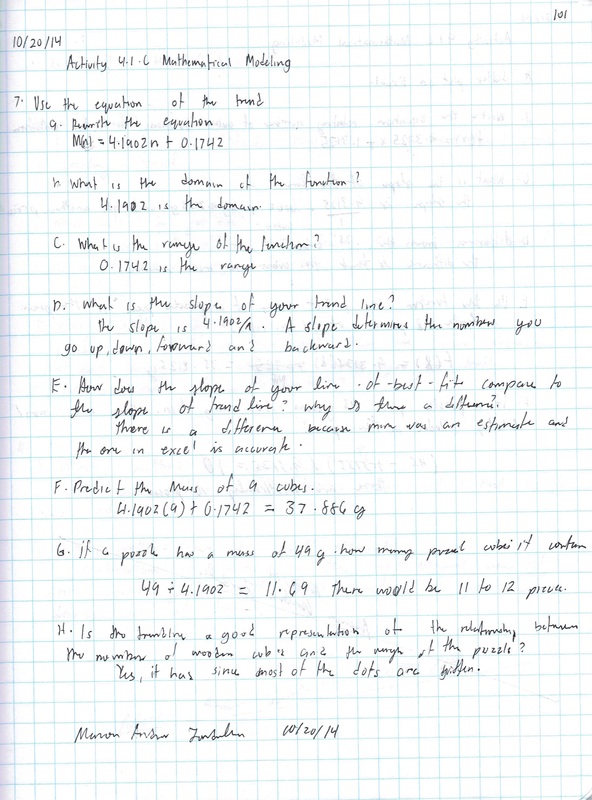
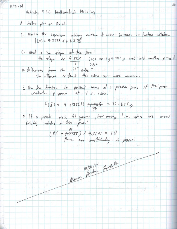
4.1.c Mathematical Modeling
In this activity you will collect and analyze data in order to make predictions based on that data. You will use both manual and computer methods to record, manipulate, and analyze the data in order to determine mathematical relationships between quantities. These mathematical relationships can be represented graphically and by equations, also known as mathematical models. You will then use the mathematical models to make predictions related to the quantities.
Unit 5
5.2 a Geometric Constraints
A CAD model can quickly display an engineer’s ideas in a realistic way. And those models can be used to generate technical drawings that can communicate the information necessary to make the idea a reality. In order to generate a 3D model, designs must start with sketches that are generated within the CAD program. These computer generated sketches will appear resemble hand drawn sketches in geometry (the combination of points, lines, and shapes), but have big advantages over hand drawn sketches. One important difference between a freehand sketch and a CAD sketch is accuracy. The lines of a CAD sketch can be drawn perfectly straight, with start and end points that occur in exact locations in space. By using numeric (dimensional) constraints a line may also be given precise length, placed a specific distance from another sketch feature, or constrained to be oriented at a specific angle from another straight line. By applying geometric constraints a line can be made perfectly horizontal or vertical. If more than one line is being sketched, they can be made perfectly parallel or perpendicular, collinear, or equal in length. Lines can be constrained to be tangent to circles or arcs, and two circles can be constrained to be concentric. In order to precisely model a part, the designer must be able to use dimensional and geometric constraints within the CAD program.
Conclusion
1. What is a geometric constraint?
Constant, non-numerical relationships between the parts of a geometric figure. Examples include parallelism, perpendicularity, and concentricity.
2. What are the different types of geometric constraints that are applied to sketches, and what are their functions?
Perpendicular-
Parallel- Causes selected linear geometry to lie at right angles to each other.
Tangent- Constrains curves , including ends of splines to be tangent to each others curves.
Coincident- Constrains other point to other geometry.
Concentric- Causes arcs and circles to have the same centerpoint.
Colinear- Causes 2 or more line or ellipses to lien on the same line.
Horizontal- Causes geometry to lie on Y axis.
Vertical- Causes geometry to lie on X axis
3. Define “tangent”.
Constrains curves , including ends of splines to be tangent to each others curves.
4. How is a geometric constraint different from a numeric constraint?
They are different because numeric constraint uses dimensions while geometric constraints, automatically locks with one click.
5.5a CAD Model Features Part 1
In order to use CAD effectively as a design tool, the designer must have the skills necessary to create, edit, and manipulate a 3D model of a part in order to create a realistic representation of an imagined object. In this activity you will build on the CAD skills that you learned in Activity 5.2b Introduction to CAD Skills. You will learn about and use additional tools and features available in most CAD programs and apply your new CAD skills to the creation of more complex parts that will be used in later activities (as components in the assembly of parts) to create complete products (including a complete Automoblox vehicle and a Button Maker machine).
5.5b CAD Model Features Part 2
Two dimensional sketches are nice, but parts have three-dimensional (3D) qualities that sketches can only imitate and communicate in an abstract manner. CAD 3D solid modeling programs can bridge the gap between 2D representations and 3D artifacts by providing an electronic representation of an object that can be moved and rotated so that all aspects of the object can be viewed.
A sketch in a 3D Computer Aided Design (CAD) solid modeling program serves as the foundation for a three-dimensional feature. Some three-dimensional features require a sketch from which the 3D form is created. Other features do not require a sketch, but instead require a three-dimensional form.
In this activity you will learn about and use additional tools and features within a CAD program to enhance your knowledge of the capabilities of the program and improve your skill in producing 3D solid models.
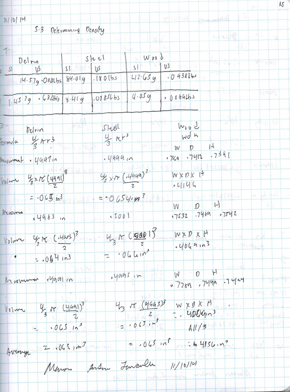
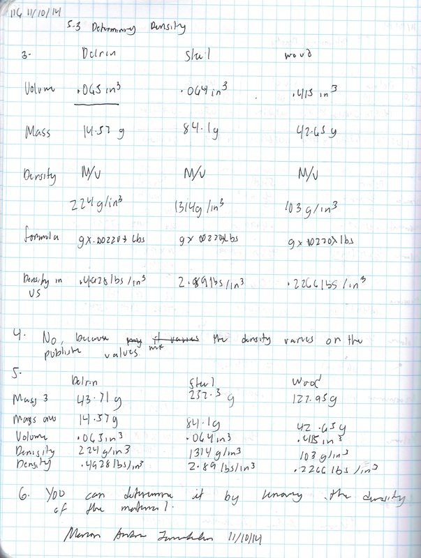
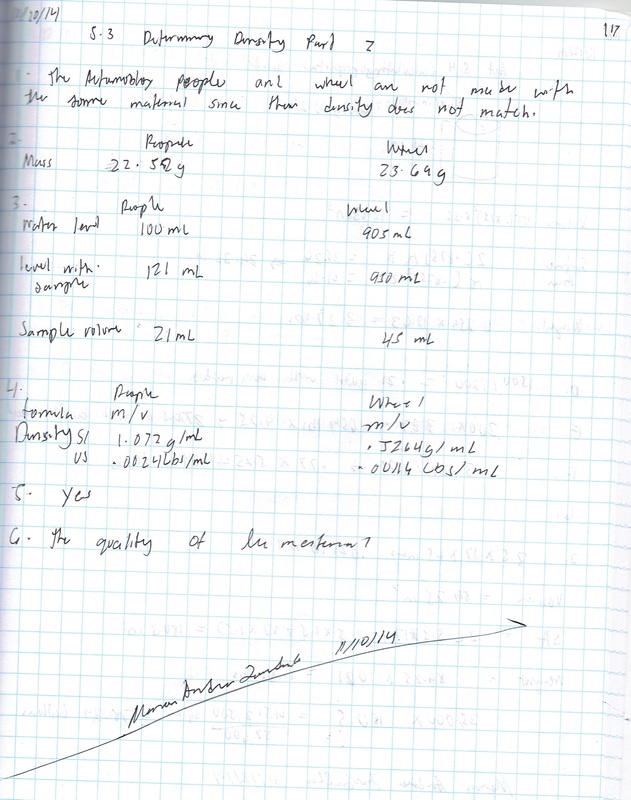
5.3 Determining Density
How full is the bag that you take to each of your classes? Can you put any more stuff into it? What happens to the size of the bag? What happens to the mass of the bag? The size of the bag likely stayed the same, though the bag itself is probably about to burst open. When the volume of something stays the same while the mass increases, then the density increases.
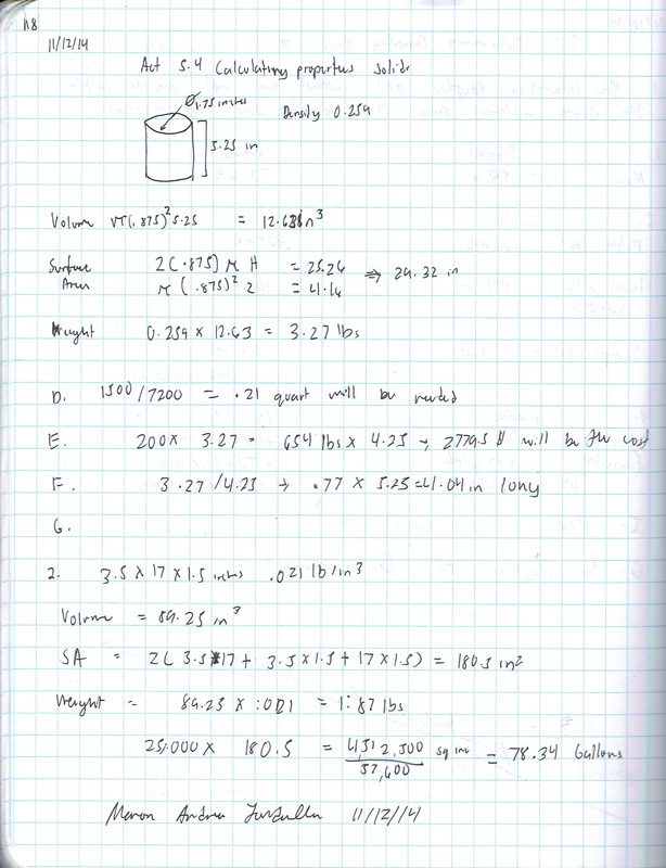
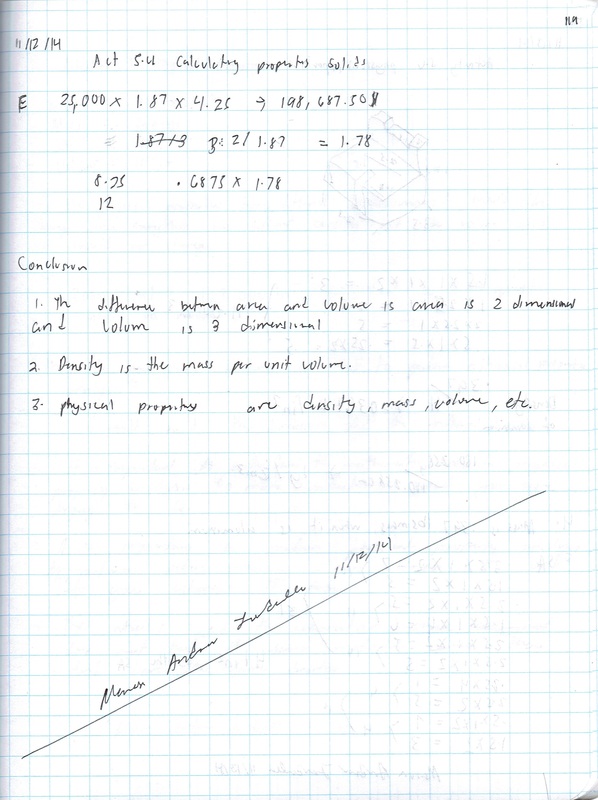
5.4 Calculating Properties of Solids
Have you ever stopped to think why it is that you are able to float in water? The reason has to do with the concept of buoyancy. The volume of water that your body displaces has weight. The weight of the displaced water pushes upward on you, while the weight of your body pushes down. If the weight of the displaced water pushing upward is greater than your weight, then you will rise out of the water to a point where equilibrium has been achieved. This means that the weight of your body that is submerged in the water, let’s say from your shoulders down, is equal to the weight of the volume of water that your body is displacing. Another way to explain this is to look at density. If your average weight density, or the average amount of weight per unit volume of your body, is less than the weight density of the water, then you will float. The word average is used because skin, bone, hair, and muscle tissue all have different weight densities. If you were to drop a coin in the water, you would notice that it sinks. The weight density of metal is higher than the weight density of water; therefore, the volume of water that is displaced by the coin cannot weigh as much as the coin itself.
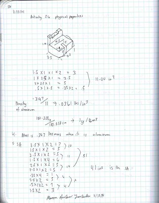
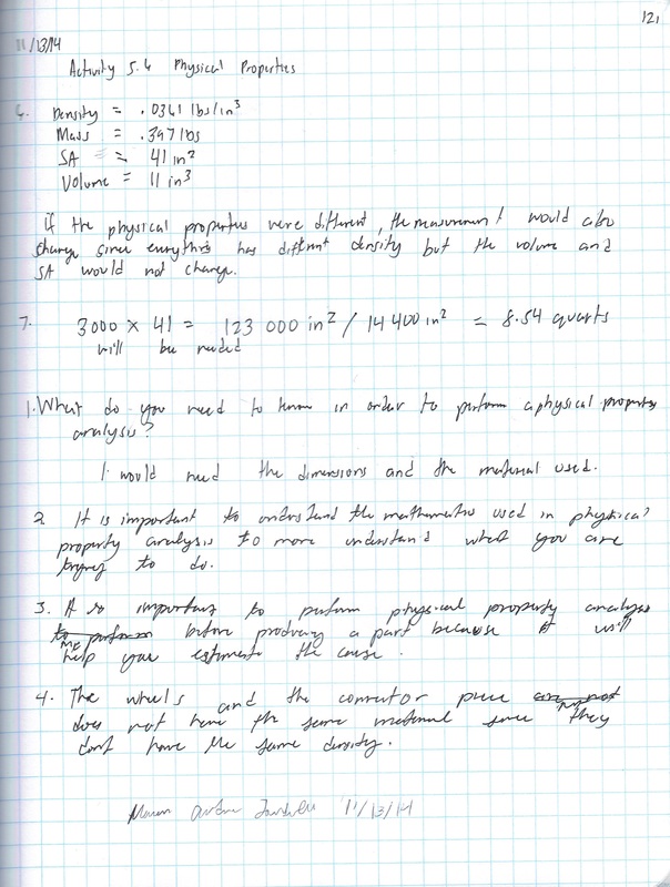
5.6 Physical Property Analysis
What do you need to know about a product before it is built? Would you need to know its volume, surface area, or weight? Would the product weigh less if it were made of aluminum or mild steel? What about copper, brass, or cast iron? How could this information impact the product design?
How can you find the properties of a product before it is built? You can calculate them mathematically, providing you have the material specifications, but it will take time. In today’s busy, fast-paced world, engineers use solid modeling software programs to speed up the calculating process. However, the user of the software must understand what the software is doing in order to estimate the answers and to be able to recognize a possible error.
How can you find the properties of a product before it is built? You can calculate them mathematically, providing you have the material specifications, but it will take time. In today’s busy, fast-paced world, engineers use solid modeling software programs to speed up the calculating process. However, the user of the software must understand what the software is doing in order to estimate the answers and to be able to recognize a possible error.
Unit 6 -
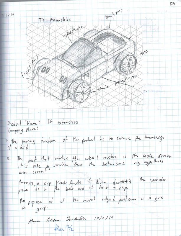
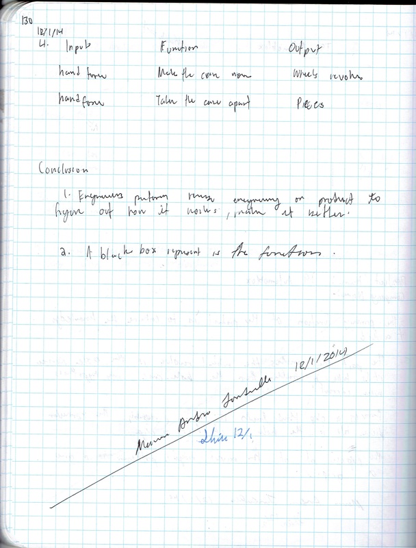
6.3 Functional Analysis
You have performed a visual analysis of your Automoblox vehicle to identify the visual design principles and elements that give the object its visual appeal, or lack thereof. The next step in the reverse engineering process involves the study of the object’s function. This is done through careful observation of the object’s sequential operation before it is disassembled. By first observing the product, you can hypothesize how a product operates and then compare your predictions to your actual findings after the part is dissected.
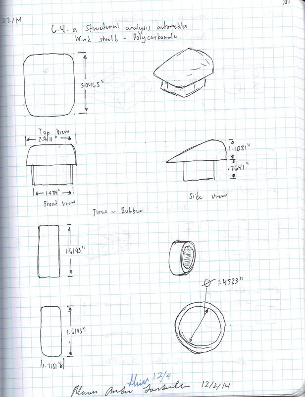
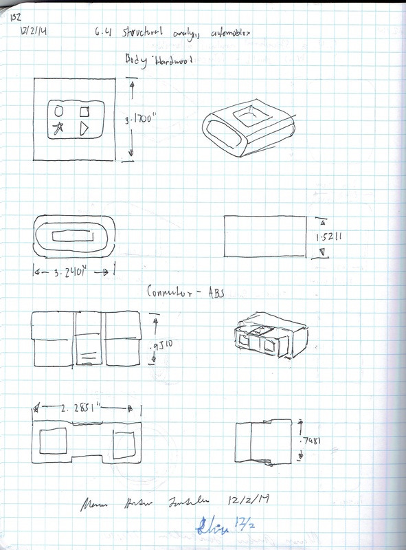
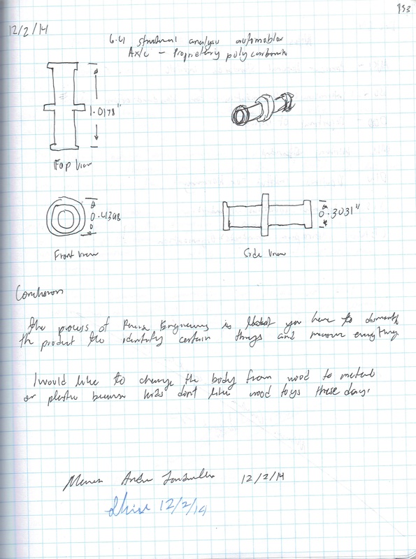
6.4 Structural Analysis
You have already performed a Visual Analysis and a Functional Analysis of your Automoblox vehicle. During this activity you will investigate vital product characteristics with regard to the structure of the product. You will research and document your findings using careful measurements, sketches, and notes which will complete the reverse engineering of your product. You will use the information you have gathered during the process in the next unit when you design an enhancement or accessory for the Automoblox vehicle.
7.1 More Dimensioning
The basic standard dimensioning method established by the American National Standards Institute and the American Society of Mechanical Engineers (ANSI or ASME) is used to apply measurement to parts to enable clear communication. In order to communicate effectively, a person needs to understand the rules of the language and to follow the standards set down so that anyone who reads a dimensioned drawing will understand the intent and then be able to manufacture the part correctly.

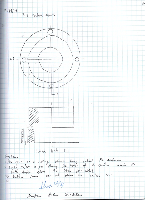
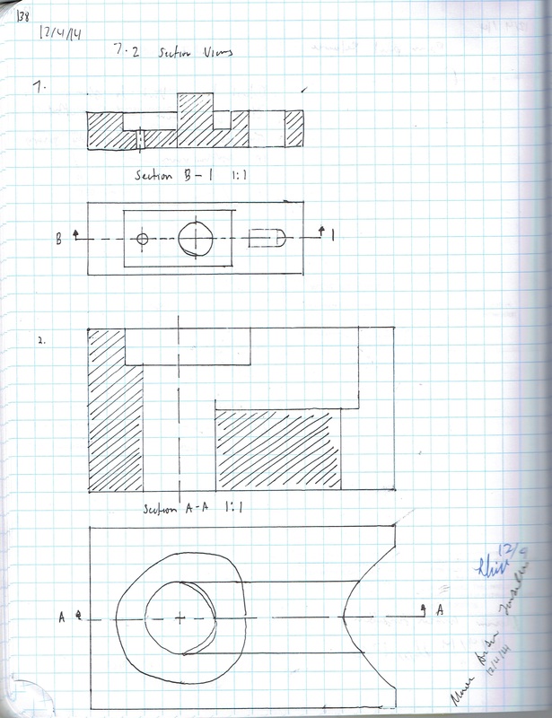
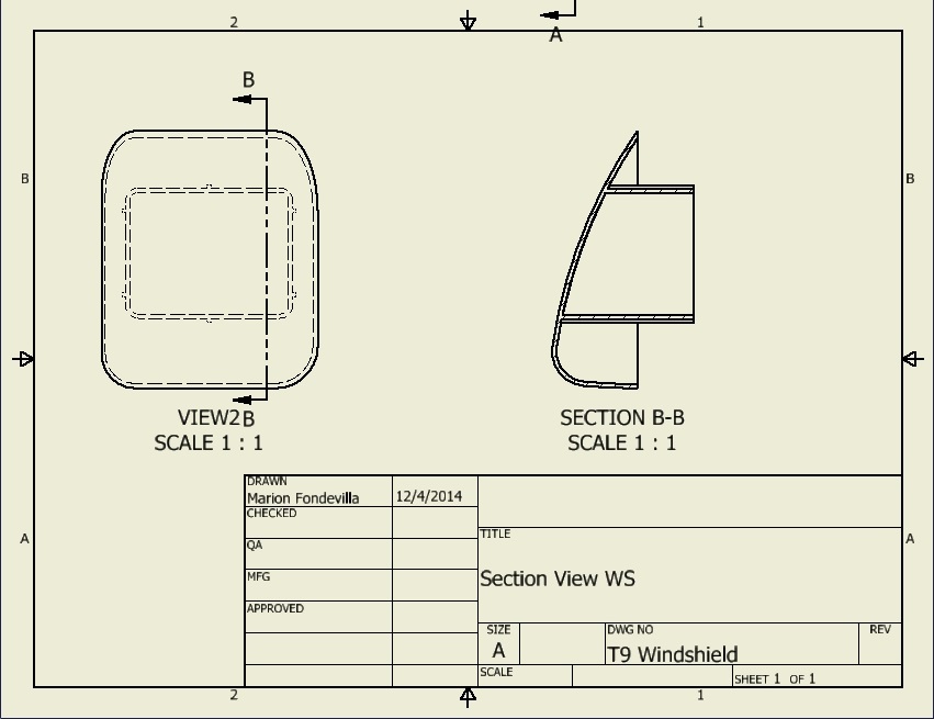
7.2 Section Views
Have you ever noticed that some objects have more going on inside than outside? Take an apple, for instance. How would you communicate the intricate details hidden inside an apple’s core? You would have to cut the apple in half in order to show someone that there are spaces inside that house seeds. If you were to make a sketch of the apple, you could show the spaces and the seeds as hidden lines, but too many hidden lines can serve to confuse the issue. Sectional views are another alternative.
The main purpose of a sectional view is to effectively communicate internal information to enhance the viewer’s understanding of the part. There are several different types of section views that engineers use to communicate internal geometry.
The main purpose of a sectional view is to effectively communicate internal information to enhance the viewer’s understanding of the part. There are several different types of section views that engineers use to communicate internal geometry.